Insulators used in overhead transmission lines and substations must withstand more than normal operating voltage. During lightning activity, transient overvoltages can place considerable electrical stress on the insulation structure. Lightning impulse withstand testing is used to evaluate how an insulator performs under these short-duration high-voltage conditions.
For manufacturers, the test is an important part of product design verification and type testing. It helps assess the dielectric strength of the insulator and identify potential weaknesses in its insulation structure.
This article explains the standard lightning impulse waveform, the main test steps, how test results are evaluated, and what to consider when selecting a lightning impulse voltage generator.
1. Why Do Insulators Need Lightning Impulse Testing?
In an overhead power system, lightning can cause transient overvoltages through direct strikes or induced effects. These voltage surges may expose insulators to electrical stresses far above their normal operating conditions.
An insulator must maintain sufficient insulation strength to prevent unacceptable electrical breakdown. Its performance depends on several factors, including:
Insulation material and structural design
Insulator length and creepage distance
Electrode and metal fitting configuration
Electric field distribution
Environmental and installation conditions
A lightning impulse withstand test applies a short-duration high-voltage impulse to the test object. The purpose is to verify whether the insulator can withstand the specified impulse voltage without unacceptable insulation failure.
This test is particularly relevant to ceramic, glass and composite insulators used in high-voltage transmission and substation applications. The exact test requirements depend on the insulator type and its applicable product standard.

2. Understanding the 1.2/50 μs Lightning Impulse Waveform
The standard lightning impulse voltage waveform commonly used in high-voltage testing is designated as 1.2/50 μs.
The two figures describe the characteristic time parameters of the impulse:
1.2 μs: The nominal front time, describing how quickly the impulse voltage rises toward its peak.
50 μs: The nominal time to half-value, measured from the virtual origin to the point where the voltage has fallen to half of its peak value.
The waveform is important because the electrical stress applied to an insulator is not determined by peak voltage alone. The shape and duration of the impulse also influence the voltage distribution and insulation response.
During testing, the measured waveform should be checked to confirm that the required impulse parameters are achieved. Waveform distortion, oscillation or excessive overshoot may affect the validity of the test.
The actual tolerances and evaluation methods must follow the applicable edition of the high-voltage test standard and the relevant product specification. A nominal 1.2/50 μs waveform should not be treated as a universal requirement for every type of insulator test.
3. Lightning Impulse Withstand Test Procedure
A reliable test requires more than generating the required peak voltage. The test object, high-voltage connections, grounding arrangement and measuring system must all be properly prepared.
The following steps describe the general test process. The detailed procedure should be adjusted according to the insulator design and applicable test standard.
Step 1: Prepare and Install the Test Object
Before testing, inspect the insulator and confirm that its type, dimensions and configuration correspond to the test specification.
The insulator should be installed in a suitable test arrangement. Its supporting structure, metal fittings and electrical connections should reproduce the intended test configuration as closely as required by the relevant standard.
Clearance distances are particularly important. Insufficient distance between the test object and nearby grounded structures may cause unintended flashover and interfere with the test results.
Step 2: Connect the Impulse Voltage Generator
The high-voltage output of the lightning impulse voltage generator is connected to the specified high-voltage terminal of the insulator.
The return path and grounding connections must be arranged carefully to avoid unwanted discharge paths. The test circuit should also be checked for loose connections, sharp edges and other factors that may affect impulse generation.
For long insulator strings or large test objects, the physical layout of the test area should be considered during system configuration.
Step 3: Configure the Measuring System
A suitable impulse voltage measuring system is required to record the applied voltage waveform.
The measuring arrangement generally includes a voltage divider, measuring cable and digital recording equipment. The measuring system must be appropriate for the test voltage and impulse parameters.
It is important to verify the measuring system before testing. An unsuitable divider or poorly arranged measuring connection may introduce waveform distortion or measurement errors.
Step 4: Apply the Specified Impulse Voltage
After checking the test circuit and measuring system, the generator is configured to produce the required impulse voltage.
The test voltage level, polarity and number of applications must follow the applicable product standard and test specification.
The operator should monitor the generated waveform and record the voltage response during each application. If abnormal discharge or an unexpected waveform occurs, the test setup should be checked before continuing.
Step 5: Record and Evaluate the Results
After the required impulse applications are completed, the test records are reviewed.
The evaluation should consider whether the specified withstand requirements have been satisfied, whether any flashover or puncture occurred, and whether the observed events are acceptable under the applicable standard.
A complete test record should include the test object identification, test circuit arrangement, applied voltage parameters, waveform records and observed results.
4. How Are Lightning Impulse Test Results Evaluated?
The evaluation of lightning impulse withstand testing focuses on the electrical response of the insulator during and after the applied impulses.
Two events need to be distinguished: flashover and puncture.
Flashover occurs when an electrical discharge travels along or around the external insulation surface, usually through the surrounding air. It may occur between the energized terminal and a grounded fitting or structure.
Puncture refers to an electrical breakdown through the solid insulating material itself. Unlike an external flashover, puncture indicates that the insulation body has suffered an internal dielectric failure.
These events should not be treated as equivalent. Their significance depends on the insulator design, test method and acceptance criteria specified in the relevant product standard.
When reviewing test results, engineers should pay attention to:
Whether the specified impulse voltage level was achieved.
Whether the measured waveform met the required parameters.
Whether flashover or puncture occurred.
Whether the number and sequence of applied impulses met the test requirements.
Whether the test object shows visible damage after testing.
A test should not be judged solely by whether a discharge was observed. The applicable standard defines the required procedure and acceptance criteria, and these must be followed when determining whether the insulator has passed.
5. How to Select a Lightning Impulse Voltage Generator
Selecting an impulse voltage generator for insulator testing requires consideration of the complete test arrangement rather than simply choosing a generator with a particular maximum output voltage.
The following factors are especially important.
Required Test Voltage
The generator must be capable of producing the impulse voltage required by the insulator's test specification.
The required voltage depends on the insulator type, rated insulation level and applicable test standard. For this reason, equipment selection should begin with the customer's actual test requirements.
Output Energy and Test Load
The energy requirement is related to the generated voltage, the equivalent capacitance of the test circuit and the circuit configuration.
The capacitance of the test object and connected components can influence the impulse generator's output performance. A generator that is suitable for one test object may not be appropriate for another.
Engineers should therefore evaluate the complete load, including the insulator, voltage divider and relevant connection components.
Waveform Adjustment
The impulse generator should provide suitable adjustment of the impulse waveform to meet the required test parameters.
The ability to configure the front and tail characteristics is important when different test objects or test specifications require different impulse conditions.
Voltage Measurement and Recording
A complete impulse testing system needs a suitable voltage measuring and recording arrangement.
The voltage divider, measuring equipment and signal transmission path should be compatible with the generator and the required measurement accuracy. Measurement capability is an essential part of the testing system, not an optional accessory.
Laboratory Layout and Future Requirements
The available installation space, grounding arrangement, safety clearances and future testing requirements should also be considered.
For manufacturers and research laboratories expecting to test different types of high-voltage insulation equipment, a properly configured system can provide greater flexibility for future applications.
6. SUTE Lightning Impulse Voltage Generator for Insulator Testing
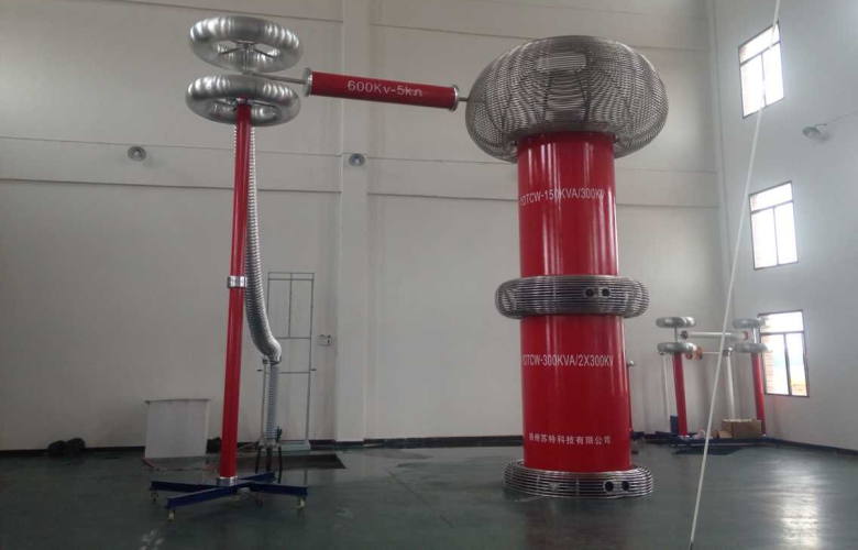
SUTE provides lightning impulse voltage generators for high-voltage insulation testing applications.
For insulator manufacturers and electrical testing laboratories, a lightning impulse voltage generator can be used to apply specified impulse voltage waveforms during dielectric withstand testing.
The system configuration should be determined according to the required test voltage, test object characteristics, waveform requirements and measuring arrangement.
Rather than selecting equipment based only on its maximum output voltage, SUTE considers the complete testing requirement when preparing a suitable configuration.
This includes the impulse generator, relevant circuit components and voltage measuring arrangement required for the intended application.
For customers planning a new insulator testing laboratory or upgrading existing high-voltage test equipment, the test object and required standards should be provided during the initial technical discussion.
Learn more: SUTE Lightning Impulse Voltage Generator
7. Frequently Asked Questions
What is the standard lightning impulse waveform for insulator testing?
The 1.2/50 μs waveform is commonly used as the standard lightning impulse voltage waveform in high-voltage testing. However, the exact waveform requirements and tolerances should be confirmed against the applicable test standard and insulator specification.
What is the difference between flashover and puncture?
Flashover is an external discharge along or around the insulation surface, while puncture is an electrical breakdown through the solid insulating material. The acceptance criteria for each event depend on the relevant product standard.
What equipment is required for lightning impulse withstand testing?
A typical test arrangement includes a lightning impulse voltage generator, a suitable voltage divider, digital measuring and recording equipment, high-voltage connections and a grounding system. The actual configuration depends on the test voltage, test object and required waveform parameters.
Technical Standards and References
The following standards provide relevant technical guidance. Their applicability should be checked against the specific insulator type and test requirement.
1. IEC 60060-1:2025 – High-voltage test techniques – Part 1: General terminology and test requirements. This is the general standard for high-voltage dielectric tests, including impulse voltage testing.
2. IEC 60060-2:2025 – High-voltage test techniques – Part 2: Measuring systems. Relevant to the approval and performance of high-voltage measuring systems.
3. IEC 60383-1:2023 – Insulators for overhead lines with a nominal voltage above 1 000 V – Part 1: Ceramic or glass insulator units for a.c. systems. Relevant to ceramic and glass insulator units within its stated scope.
4. IEC 61109:2025 – Insulators for overhead lines – Composite suspension and tension insulators. Relevant to composite suspension and tension insulators within its stated scope.
Note: The general testing principles discussed in this article do not replace the specific test procedures and acceptance criteria in the applicable product standard.